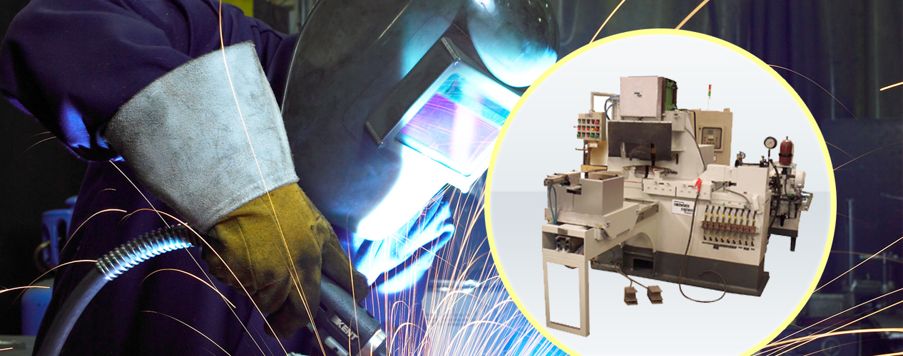
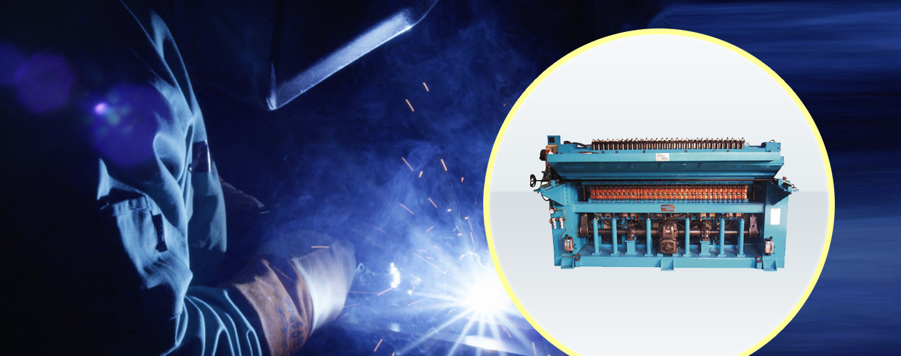
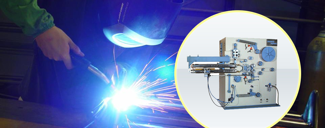
Flash Butt Welders
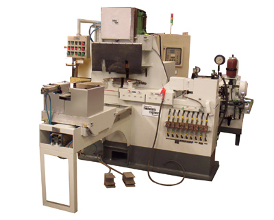 |
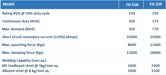
| These machines are robust in construction and are precision-built for long trouble-free service. Each machine is submitted to rigorous proving tests before delivery, so that the machine is ready for immediate installation and operation at the customer's works. The Know-How that enables MECHALONIC ENGINEERS to offer these machines is backed by many years of experience in Welding Technology. These Flash Butt Welders are specially designed for heavy duty applications where repeatability in performance is very important. Tooling and clamping devices are available for adapting these machines for the manufacture of railway shackles, automotive parts, starter ring-gears, wheel rims, link chains, etc. For accurate and consistent weld results fully solid-state electronic controls are provided. Semi-automatic and fully automatic modes of operations are possible. Machine incorporating PLC and SERVO System are also available on request. These machines conform to the latest National / International Standards. Specifications: Standard Ratings: 150, 200, 250 KVA (Higher capacities available on request). Type of Machine FH - Series: Automatic and semi-automatic high-speed flash Butt Welding Machine with hydraulically operated clamping and upsetting mechanism. Construction: Main frame assembly is of sturdy, all-welded steel plate fabrication suitably braced and stiffened at points of stress to minimise deflection and thermally stress-relieved; the transformer placed separately from the main frame and connected through flexible connectors. Left hand platen is fixed and right-hand platen is movable and guided on precision - hardened and ground slides with provision for wear adjustment. Welding Transformer: Transformer is of special type conforming to IS: 4804 Part I - 1968 and TWMA Standards. Water cooled, having core of high grade electrical steel, primary and secondary coils of solid electrolytic copper of ample section, heavy duty class 'F' insulated and encapsulated and suitable for withstanding severe loading conditions. Thermostatic protection has been provided against overheating of the transformer. In case of overheating, the control circuit opens, thereby preventing its operation till normal condition is attained. Current Control By Transformer Taps: Transformer primary coil provided with taps brought out to tap changing links for adjustment of welding current in 4 steps from 50% to 100%. Tap change links are enclosed behind the machine panel. Cooling System: Transformer, secondary bus bars and electrodes and thyristors are water-cooled. Internal water-cooling piping is provided in the machine. All circuits terminate into a single outlet. Water Flow Switch: (Optional accessory at extra cost). Water Flow Switch shall be provided with machine to ensure adequate flow of water while operating the machine. When sufficient flow of water is not provided the control circuit trips off and machine stops. Visual indication shall also be provided to indicate inadequate flow of water. Clamping & Tooling: Clamping pressure applied by individual hydraulic cylinder through either alligator-type lever operated clamps or vertical clamp slides depending on job configuration. Upper and lower tooling fitted with one set of replaceable electrodes / dies to suit particular geometry of the components. Pre-Heat, Flashing & Upsetting: A movement of right-hand platen is effected by a direct acting hydraulic cylinder. Provision is made for automatic pre-heating of the work pieces prior to the commencement of the flashing operation. The retractable cylinder facilitates only a small stroke of the cylinder to be operational during this period. The ON and OFF timing periods of pre-heating are separately controlled by precision electronic timer having a range of 2-250 cycles continuously adjustable. The numbers of pre-heat cycles are selected from 0-99 impulses in steps of one impulse. Flashing parameters such as the initial speed, rate of acceleration and final speed are under the control of a flow control valve. This valve determines the initial speed of flashing and acceleration and final speed achieved by the moving platen at the pre-set distance. Upsetting is achieved by bypassing the flow control valve and dumping the oil suddenly. Upsetting pressure can be varied by means of pressure regulating valve. Cutting off the current just after the application of the upset force is controlled by precision electronic timer. Welding current interrupted automatically after pre-adjusted interval starting from the moment of upsetting by an Electronic timer unit adjustable to suit any welding requirement. Post-Heat(Optional at extra cost): A post-heat timer and a programmable 6-second downslope control of absolute accuracy enabling excellent post-weld heat treatment to the weld heat treatment to the weld joint can be provided at extra cost. Contractor: Heavy-duty Thyristor Contractor incorporated in the primary circuit for on/off switching of the set. Main power contractor is chosen as per the requirement of the welding machine. Two high Power thyristors on a water-cooled heat sink are connected in anti-parallel. The gates of the thyristors are connected to the firing circuit, which triggers the firing signals to the thyristors. The thyristors are protected from voltage and current surges by conservative designs. A thermo switch mounted on the water-cooled heat sink offers additional safety to the Thyristors. Servo Control(Optional at extra cost): Control functions such as Pre-heat, Flashing, Upsetting and Post Heat, which are done with Non-synchronous timers and relay logic is replaced with a compact PLC with appropriate programming. The right hand side platen movement is controlled by means of a Servo Valve having position feed back (with the help of Linear Transducer) and current feedback for proper flashing and upsetting. Pressure feed back is also applied to the Servo system during pre-heating for fast and controlled heating. Flashing parameters such as initial speed, rate of acceleration, flashing speed, etc. are controlled with the help of servo valve to get optimum results. Hydraulic Power Pack: The hydraulic power pack is an integral unit, consisting of a tank, strainer, pumping unit, heat exchanger and the group of valves and devices as per the circuit of the system arranged for easy servicing. Only the hoses are to be connected to the bulk heads provided for starting up the hydraulic system. It is powered by a 3-Phase Induction Motor. Service Requirements Supply Voltage: 415 Volts, Single Phase, 50 Hz. (2 lines of 3-phase supply) for transformer. 415 Volts, 3-Phase. 50 cycles, for hydraulic power pack as given in technical specification. Main Supply Disconnect Switch: To be provided by customer. 2-Pole, Isolating Switch Unit (rating as recommended). And 3-Pole, Isolating Switch Unit (rating as recommended). Mains Supply Cable: To be provided by customer, 2-Core, copper/aluminium conductor (rating as recommended). And 3-Core, Copper / aluminium conductor (rating as recommended). Water: Customer to provide water supply of recommended flow rate, free from residue forming impurities and at a temperature less than 30oC. Technical Data |
| Technical Data |
 |


